Stamp
Intro
The basic stamp stroke rendering is pretty intuitive. We are given a texture called stamp texture or footprint. While a user paints on a canvas, we render the texture onto the canvas equidistantly along the drawing trace. When the textures are close enough, they seem continuous and form a stroke.

Artists love to create stamp brushes since their expressiveness and intuition. More than 90% of brushes in popular paint software are stamp brushes. Researchers and developers have developed dozens of extra parameters that can apply various aspects of stylization on a stroke. How to replicate these parameters with GPU acceleration is under-researched. Therefore, we will focus on the most critical technique, how to place the footprints in a shader program.
A naive solution is to place a footprint at each vertex.
 Place a dot texture at each vertex.
But it's not good enough for the most usages. The rendering result of strokes depends on polylines' vertex density. After subdivision, simplification, or deformation of the polylines, the strokes get denser or sparser appearance, which ruins the rendering result. We must develop methods that rendering is independent of vertex density, just like rendering 3D meshes. Therefore, I will introduce how to place footprints equidistantly along a polyline.
Locate stamps
When rendering with CPU, calculating where to place footprint (stamp positions) on a polyline is pretty straightforward. Start from the very first vertex of the polyline, place the footprint on the canvas, move along the polyline with the stamp interval to the next stamp position, loop until reach the end of polyline. If we use an image processing library and therefore don't worry about details in placing the footprint, the whole process can programmed within 10 lines of code.

GPU implementation is more challenging, but still relatively straightforward. We use the same approach as rendering a vanilla stroke: Placing the four new vertices for each edge in the vertex shader (or the geometry shader). The difference only comes to the fragment shader.
We will calculate the stamp positions in the fragment shader. At each polyline vertex, we compute its distance to the first vertex along the polyline. The distances represent the cumulative length of the edges, and we calculated them with [Prefix Sum]wiki algorithm.

Parallel prefix sum
There are parallel prefix sum algorithms can be implemented with compute shaders, wiki. By using one of them, the whole rendering process is GPU-accelerated.
The best tutorial about parallel prefix sum I've ever found is this free course High Performance Computing by Prof. Rich Vuduc. The course introduces prefix sum in Lesson 6.
Since we place stamps equidistantly, we can calculate these positions in all pixels involved in each edge. Then a pixel can loop through the positions, sample the stamp textures and determine its color. We compute the texture coordinate with the pixel's distance to the stamp positions and radii.
Loop and sample stamps
A pixel can loop through all stamps on the edge invokes it. But the edge can be very long and has many unnecessary stamps for a pixel to loop through. We want to constrain the loop within only a segment of the edge, within which stamps can cover the current pixel. Given the pixel , we can get this segment by solving the geometry shown in the figure below.

I label the segment can cover the pixel with the thicker black line. The two dashed circles intersect at . I label their centers with vertical line ticks, which are the start and end points of the segment. The centers are the farthest points where a stamp placed can cover the pixel . Any stamps outside the segment have no chance to affect the pixel's color.
In order to get start and end points' positions, we have a geometry puzzle to solve:
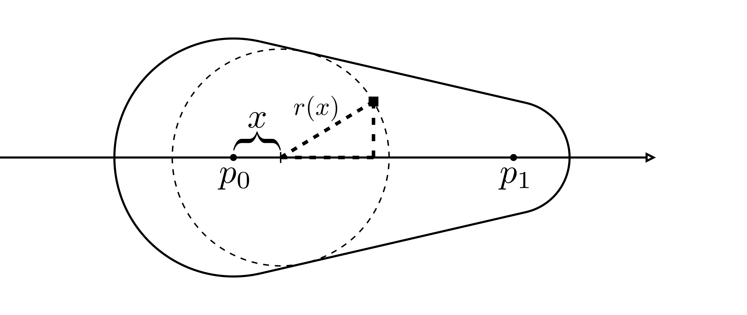
As the figure shows, we set up the same local coordinate as vanilla stroke in the shader program. as the origin and X and Y axes align to the tangent and normal direction, as the pixel's local coordinate. is the furthest point's x value. By calculating it, we know the position of farthest point. The distance from the pixel and the furthest point is the radius of the furthest point, whose value is determined by x. To solve the unknown , we can set an equation from the dashed right triangle.
It's not hard to derive from the figure below.
is the length of the current edge.
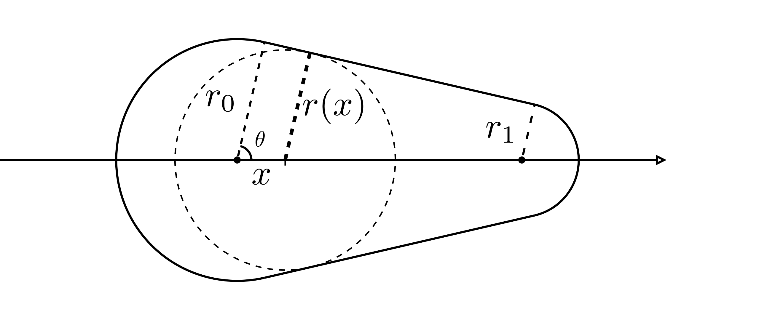 By replacing , we get a quadratic equation :
Remind that . Applying the formula for solving quadratic equations, two roots of the equation are the X value of min and max points of the segment. Therefore, we know the range in the fragment shader and pixels only loop through stamps that can cover it.
- vertex.glsl
- fragment.glsl

You can use RGBA values sampled from footprints directly, like what I did here. But for the most common scenario, we set RGB values with users' brush setting and sample alpha values from a monochrome texture, whose pixel's gray scale determines the opacity. Here is the pseudocode in the fragment shader:
uniform vec3 RGB; // Users' brush setting
void main(){
    float A = 0.0;
    for each stamp
    {
        // Only sample opacity value from the footprint.
        float opacity = texture(footprint, textureCoordinate);
        // Apply alpha compositing to get the final alpha value.
        A = A * (1.0-opacity) + opacity;
    }
    outColor = vec4(RGB, A);
}
Furthermore, we can apply random rotation or noise on each footprint to stylize the stroke.
The stamp index values currIndex are very helpful to generate consistent random numbers as seed values.
Square footprint
I introduce the brush rendering with the assumption that footprints are constrained within a dot area, which is the most common case in practice. But it's not for all. Area outside the dot area plays a critical role sometimes. If it is necessary to render square footprints, I guess you can instantly come up with a new approach to placing the vertices and determining stamp positions. But they may hurt the performance and have complex logic to implement.
I will introduce a very tricky approach to rendering the square footprint, and meanwhile, improving the rendering performance and reducing the complexity of the shader code. All we have to sacrifice is the "correctness" of geometry, which is a minor concern for artists.
We place vertices a little bit differently from before. Instead of offset vertices by and along the normal direction, we just offset and value, as the figure below shows.
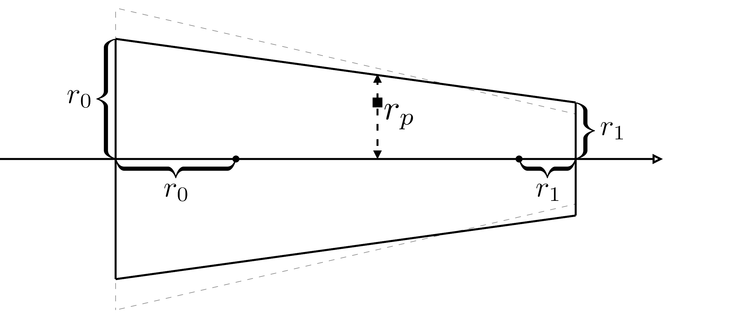
The solid line trapezoid shows the new approach to place vertices. Dashed grey line trapezoid shows the original approach.
In the vertex shader or geometry shader, we put the radius value to the left two vertices, to the right two vertices, and let fragment shader interpolate the values for us. Then we get an interpolated radius value in the fragment shader. You can prove this is the stroke radius value across the current pixel as the figure shows. We assume the whole stroke is uni-radius and program the shader with .
- vertex.glsl
- fragment.glsl
You can find the shader code is simplified because we don't need to compute two roots of the quadratic equation. Besides, I cannot perceive any deformation caused by the trick without careful investigation.
To see the deformation more clearly, I replace the footprint with a wireframe square. Obviously the squares are squeezed or extruded along the stroke.
It's hard to explain the deformation mathematically, but for the common practice, the result is better since we can render square footprint.